In military application, printed circuit board must be highly reliable, especially for sensors used in extreme environments. Military PCB differ from standard PCB in that they must function properly under extreme condition, including dealing with contaminants, chemicals, and extreme temperature. While conventional PCB design are not typically exposed to these harsh environments, in military PCB are often required to meet these challenges.
This article will answer six important question about military circuit boards. It will give you an understanding of military circuit board application scenarios, materials, and standards for military-grade PCBs. As well as what you need to look for in the design, manufacturing and assembly process to bring PCB up to military standard.
Where Are Military PCB Used?
Military PCBs are used in a wide variety of military applications covering:
- Communication systems: radio and satellite communications
- Tracking systems: radar and sonar
- Aircraft electronics systems: aircraft navigation, communications and weapons control
- Missiles and weapons control: precision guidance and integration of fire control systems
- Drones and Ground Vehicles: military drones and armoured vehicles
- Naval Systems: Naval Ships and Submarines
- Electronic Warfare and Countermeasures Systems: Signal Jamming, Intelligence Gathering, and Countering Enemy Electronic Systems.
- C4ISR systems: command, control and intelligence systems
- Space-based and cyber security systems: military satellites and cyber security systems
In the complex and volatile environment of the battlefield, where equipment downtime can have serious consequence, the military need these circuit board to operate stably under all circumstances. Therefore, to ensure the reliability and durability of the equipment, military PCB must meet strict standards and specifications.
What Are the Standards for Military PCB?
Military grade PCB manufacturer need to comply with a number of stringent certifications and standards to ensure that their product meet the high reliability and quality requirement for defence and military applications. These standard cover not only design, manufacturing and testing, but also import/export regulation and quality management. The following are the main standard and certification that specifically need to be followed:
1.ITAR
ITAR is the International Traffic in Arms Regulation, which strictly control the import and export of US defence-related product and technologies. Military PCB manufacturer, as well as companies engaged in the export of defence products and technical data, must ensure that all activities comply with ITAR regulations to safeguard defence data and products.
2.MIL-PRF-31032
Developed by the U.S. Department of Defense (DoD), this standard specifically regulates the performance requirements for high reliability PCB. MIL-PRF-31032 cover PCB material, manufacturing processes, quality control, and testing procedures. Its detailed information is available on the DoD website as a performance benchmark for various weapon systems and military programmes.
3.MIL-PRF-55110
MIL-PRF-55110 defines qualification and performance requirements for single-sided, double-sided, and multilayer rigid PCBs for use in military systems. The standard applies to boards with or without plated through-holes and is also governed by the US Department of Defence for ensuring the reliability of rigid PCBs in harsh environments.
4.MIL-STD-810
This standard focuses on environmental engineering design and testing to simulate PCB performance in extreme environments (e.g., temperature shock, humidity, vibration, salt spray, etc.). PCB that pass the MIL-STD-810 test are able to operate stably for a long period of time under various harsh condition.
5.MIL-STD-461
This is the standard on the EMC requirement of the PCB to ensure that it will not be subjected to external electromagnetic interference, but also does not cause interference to the surrounding electronic system. This is vital for military communication equipment and radar system.
6.IPC-6012 Class 3/3A
IPC-6012 is a standard developed by the Institute for Electronics Industry Connectivity (IPC) that specifically defines the requirements for Class 3 and Class 3A PCB for military and mission-critical application. These standard present strict tolerance controls for high performance performance of PCBs in harsh conditions. class 3A is particularly targeted at military and avionics equipment and is one of the most stringent standards in PCB manufacturing.
7.AS9100
AS9100 is a quality management standard for the aerospace industry that combine the best practice of ISO 9001 with additional quality requirement. The standard ensure that manufacturers' product meet the stringent quality requirement of NASA, DOD (US Department of Defense) and FAA (Federal Aviation Administration).
How Should I Choose the Materials for My Military PCB?
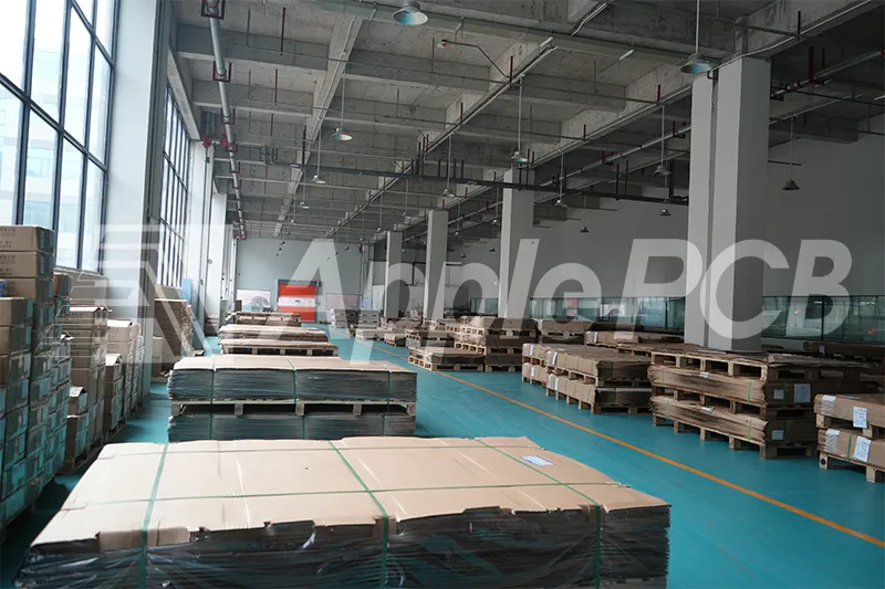
When selecting a military PCB substrate it is important to consider whether the characteristics of the substrate will meet the specific environmental condition of the military application. Below are some common military PCB substrate characteristics and application scenarios.
| Substrates | Specificities | Applications |
| Polyimide | High Thermal Resistance, High Mechanical Strength | Aerospace, UAVs, Military Electronics |
| PTFE | Low Dielectric Constant, Excellent Electrical Performance | Radar Systems High-Speed Communication Devices |
| Ceramic | High Thermal Conductivity, High Mechanical Strength | High-Power Military Electronics |
| High Tg FR-4 | Flame Retardant, High Temperature Resistance | Basic Military Systems, Power Control Boards |
| Aluminum | Good Thermal Conductivity | High-Power LED Equipment |
| Risholite | Epoxy and Phenolic Resin Laminate | Heavy machinery Control Systems |
| Getek | Low Dielectric Loss Laminate and Prepreg, Low Signal Loss | High-Speed Signal Data Processing Systems |
| High-Temperature Laminate | High Thermal Resistance | Missile Systems, Fire Control Equipment, High-Power Radar |
What to Consider When Designing Military PCB?

1.Durability
Military PCB must be able to cope with intense environmental stresses such as temperature cycling, vibration and shock. Therefore, in order to enhance structural stability, the design should use thicker copper layer, larger pad size, wider alignment and mechanical fastening points to improve the board's resistance to damage.
2.Thermal Management
High-power system generate a lot of heat, so they need to be effectively dissipated by designing large copper planes, polygonal alignments, thermally conductive dielectrics, and thermal vias to ensure continuous and stable operation under high loads.
3.Mixed-Signal Circuit Design
Military PCBs often need to handle sensitive analogue signals and noisy digital signals at the same time. The design needs to reduce the interference between the signals through circuit partitioning, wiring protection, grounding and reasonable layout of components. Aluminium case shielding can be used to protect clock signals and critical RF signals against EMI problems.
4.Component Selection
To ensure the reliability of the system, high-precision components should be selected. That is, use military standard components with low tolerances (1-2%) rather than common components with 5-10% tolerances.
5.Current Management
In order to cope with peak currents, the design should reserve extra current capacity by using short alignments, thick copper layers (3-4 ounces per square foot), and with heat dissipation techniques.
6.Aspect Ratio and Through-Hole Design
A through-hole aspect ratio of 10:1 or less and a maximum board thickness of no more than 100 mil are recommended for reliability in harsh environments.
7.Planar Separation
To use separate power and ground layers to isolate low-frequency components from high-frequency components and reduce signal interference, the minimum dielectric thickness between planar layers should be kept above 3.5 mil.
8.Drilling Design
For inner and outer design, the pad width around the drilled hole should be 6-7 mil and the clearance between the drilled hole and the copper layer should be 7-8 mils to ensure board electrical performance.
In addition, for some specific harsh conditions, we can carry out targeted design to meet the application requirements.
| Acceleration and vibration | Improved component adhesion with through-hole assemblies Symmetric stacking with uniform copper distribution |
| Lightning protection design | Integrated surge protection circuitry Use of materials that can withstand transient high voltage |
| Radiation protection | Uses radiation-resistant components that meet MIL-PRF-38535 standards Uses anti-fuse assembly technology |
What to Consider When Manufacturing Military PCB?
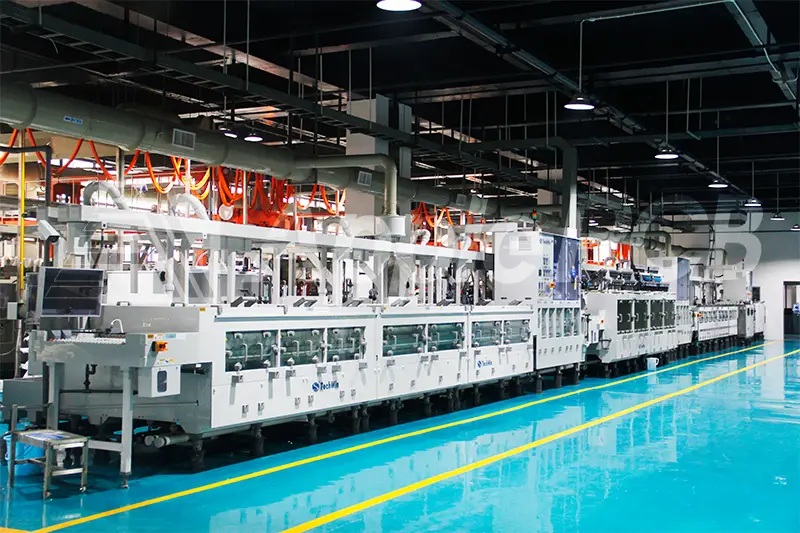
1.Material Selection
In addition to the substrate mentioned above, the choice of copper foil will also have an impact on the military PCB. Usually we want to use calendered copper or calendered copper alloy foils because they have excellent surface smoothness and good mechanical properties. In addition, military PCB usually use 1-3oz thick copper to enhance the current carrying capacity.
2.Surface Finish
In the military PCB, it is better to choose the surface finish with better durability such as immersion silver, electroless nickel and immersion gold and hot air solder levelling.
3.Solder Mask and Legend
High temperature epoxy solder mask should be used to withstand extreme environment and to avoid component detachment and circuit damage. MIL-PRF-31032 specifies the type and standard of mask available.
4.Structure and Process Design
Try to use high-density interconnection technology, arrange blind and buried holes in limited space, and combine with scoring/routing design to enhance structural robustness and reliability.
5.Quality Control
After the completion of the finished product manufacturing also need to carry out appearance checks, dimensional measurements, electrical performance tests to ensure the reliability of the military PCB. In addition, according to the use of military PCB environment for thermal shock test and humidity test and other environmental testing to ensure that the PCB in extreme conditions can still work properly.
What to Consider When Assembling Military PCB?
1.Assembly Environment
The workplace should be well ventilated and well lit, the temperature should be controlled between 15°C and 35°C, and the humidity should be kept within the range of 30% to 75%. In order to ensure the quality of military PCB assembly, dust, dirt, insulator debris should be removed from the site in time. At the same time, anti-static measures need to be taken, such as the use of anti-static table mat, in order to avoid static damage to military SMD.
2.Component Cleaning
Inspect the leads of the components for oxidation or dirt before military PCB assembly. If necessary, sand the lead surface with special metallurgical sandpaper until the oxide layer is removed. After removal of the oxide layer, tinning should be completed within 2 hours. Take care that the cleaned leads are not touched directly by hand to prevent secondary oxidation.
3.Component Installation Order
Military PCB components need to be installed in accordance with the ‘low and then high, small and then large, light and then heavy, easy and then difficult’ order. General components should be installed first, the special components are left until the last processing, and to ensure that the previous step will not interfere with the subsequent steps. When installing, component logos and markings should be clearly visible and arranged as far as possible in a left-to-right reading direction for easy identification and inspection.
Final Thoughts
The manufacture and design of military PCB is a complex art, involving exacting standard and multiple consideration. This article has answered only six of the main questions, and more in-depth discussion is needed to gain a fuller understanding of this field. If you have any further questions or PCB project needs, please feel free to contact us via the bottom right corner of the page. ApplePCB's team of engineers has over 15 years of experience and we are confident that we can provide you with professional support and solutions to help your project succeed.

