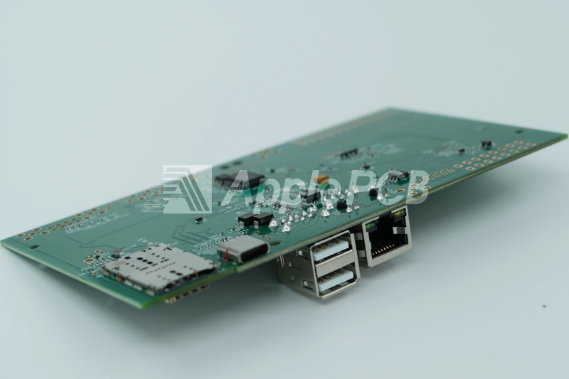
PCB connector is a key component in the electronic system, its main role is to establish a reliable power and signal transmission channel on the printed circuit board. Whether connecting multiple boards or connecting different component on the same board, PCB connectors ensure the stable operation of electronic systems.
Structure of PCB Connectors
- Shell: made of insulating materials such as plastic or ceramic to provide mechanical protection for the internal components and to ensure electrical isolation between neighboring connectors.
- Conductive part: mainly includes contacts (can be in the form of pins, sockets or edge connectors) and internal current-carrying components (such as terminal strips, metal strips). These parts are usually made of materials with good conductivity and corrosion resistance, such as copper, to ensure that signals can be transmitted stably from the starting point (terminal A) to the end point (terminal B).
Advantages of PCB Connectors
- Modularized design for easy assembly and maintenance of electronic systems.
- Reduces reliance on conventional soldering, soldering irons, and insulating tapes
- Provides a safe and reliable connection
- Supports a variety of connection technologies (e.g., SMT, THT, or pin-to-pin) to accommodate different applications.
PCB Connector Selection Process
PCB connector selection process is a key link in the early stages of the project, a reasonable selection can be avoided later rework and cost increases. Specific processes are as follows:
1.Mechanical Characteristics Assessment
- Confirm the operating environment temperature range
- Evaluate the humidity and corrosion requirements
- Select materials to meet environmental conditions
2.Electrical Parameter Verification
- Calculate the maximum operating current
- Check the current margin
- Evaluate overcurrent protection requirements
3.Dull Proof Design
- Avoid using the same type of connector
- Use different specification or key design
- Ensure unique pairing
4.Signal Integrity Analysis
- Separate power and signal connectors
- Assess the risk of dangling pins
- Ensure safe operation of the chip
5.Pin Definition
- Plan the pin order of the male header
- Determine female header correspondence
- Verify signal distribution
6.Connection Verification
- Check PCB layout and harness matching
- Check the correct signal alignment
- Confirm the reliability of electrical connection
Types of PCB Connectors
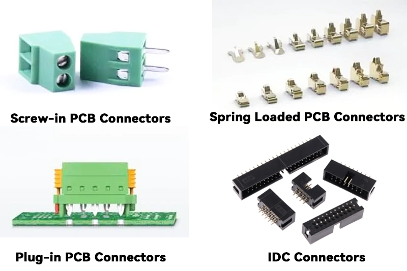
Screw-in PCB Connectors
Screw-in PCB connector or commonly referred to as screw terminal or terminal cap. They are a form of wire connector that is very reliable. These connector are suitable for different size of wire and are available in P1, P2, P3, P4, P5 and P6 depending on the size of the wiring and the thickness of the wire.
To properly install a screw-type PCB connector, follow the steps below:
1.Preparation for threading: The outer jacket of the wire need to be stripped by removing a small portion of it to expose the metal conductor. Then one is required to pull the wire through the socket at the bottom of the connector ensuring that the end of the wire well makes contact with the metal conductor within the connector.
2.Connecting additional wire: In case there are more than one wire which require connection, the extra wires have to be pulled into the designated slots in a manner.
3.Tighten to secure: Use the screw swivel cap to gently tighten to ensure that the wire is securely clamped.
Spring Loaded PCB Connectors
Spring PCB connector are component that utilize the elastic properties of spring to make electrical connection. They are available in a variety of configuration, including board-to-board connector, target connector, and terminal blocks for a wide range of industrial applications. It is also easy to install without the need for special tools, greatly reducing installation time.
The installation steps for spring loaded PCB connector are as follow:
- Polarity identification: Confirm the markings on the connector (e.g. “+” and “-”) to ensure that the positive and negative pole are correctly aligned.
- Operate the spring-loaded tab: Use a screwdriver to gently press the spring loaded tab to open the wire insertion port.
- Insert the wire: Insert the stripped wire into the opening, release the tab and use the spring pressure to fix the wire.
- Secure the connector: If the connector has screw hole, use the screw to securely install it in the specified location.
When using spring loaded PCB connector, make sure that the wire diameter meet the specification of the connector to avoid poor contact. When operating the spring loaded tab the force should be moderate to prevent damage to the spring mechanism.
Plug-in PCB Connectors
Plug in connector establish an electrical connection through a simple plug-and-play operation. They usually consist of pins or socket. It is simple to connect the female end by connecting a wire to the male end of the connector and then inserting the male end into the female end.
This plug-and-play design makes it easy to connect and disconnect components of electronic devices without soldering. Therefore, it is particularly suitable for applications that require frequent connection and disconnection of components.
IDC Connectors
The IDC connector is a special PCB connector that utilizes “insulation piercing” technology. This connector is unique in that the connection can be made without stripping the insulation from the wires. This innovative method of connection significantly increases the speed and efficiency of the connection. Due to its high efficiency, the IDC connector is particularly suitable for application scenarios where a large number of wires need to be connected, such as autonomous driving systems.
Points to Consider When Selecting PCB Connectors
The type of PCB connector are very wide, to ensure that the selected connector can meet the nee of a particular application, it is necessary to comprehensively consider a number of factors to ensure that the selection of the most suitable for the application requirements of the connector.

1.Carrying Capacity
When choosing the power signal connector, the first thing to focus on its current-carrying capacity. Need to be based on the actual current requirements for the design of the derating, to avoid damage to the connector due to overload. In addition, attention should also be paid to the insulation between the connector pins to ensure safety.
2.Structure Size
The external dimension of the connector are very important, especially in application where space is limited. Ensure that the connector does not interfere with other component, and select the appropriate mounting (such as front mounting, rear mounting) and fixing method (such as rivets, screw, snap rings, etc.). For the shape design, you can choose straight, curved, T-type, round or square type according to the requirement.
3.Shielding
With the increase of electromagnetic compatibility (EMC) requirement, it is also necessary to choose connector with metal shell. The shielding of the cable should be effectively connected to the metal shell of the connector to prevent electromagnetic interference. It is also possible to use an injection molding process to wrap the copper skin around the plug area and solder the shield to the copper skin to achieve good shielding.
4.Impedance Matching
Some signal, such as RF signal, have strict impedance matching requirements. Mismatch will cause signal reflection and affect the quality of signal transmission. For general signal transmission, the impedance matching requirements of connectors are relatively loose, but RF applications require special attention.
5.Misconnection Prevention
First a connector with an error-proof design can effectively avoid incorrect connection caused by rotation or misalignment. Second, when the same type of connector is used for multiple signals, the interfaces must be differentially designed to prevent the serious consequences of a Class A connector being mistakenly inserted into a Class B interface.
6.Reliability
The reliability of connector is critical, especially when used over long period of time. Face contact is more reliable than point contact, and pinhole connector are superior to leaf spring connector. Therefore, priority should be given to designs with more reliable contact methods when selecting to ensure stable signal transmission.
7.Use of the Environment
The selection of connector need to fully consider the actual use environment. For example, in extreme environment such as high temperature, high humidity or salt spray, corrosion resistant metals and thermally stable polymer material should be selected. In industrial and automotive environment where mechanical stress such as vibration are likely, it may be necessary to incorporate a locking mechanism into the PCB connector. This locking design help prevent the connector from loosening or falling out due to vibration or shock.
8.Charged Considerations
According to whether the connector is often charged, select the appropriate pin or hole type connector. Under charged conditions, special attention needs to be paid to the connector's insulation performance and contact reliability to avoid the risk of short circuit or poor contact.
9.Locking Function
In order to avoid the connector in the use of the process of loosening, to ensure good contact, the choice of connectors with locking function is very necessary. The locking design can effectively prevent the connector from falling off under vibration or other external forces.
10.Cost
Cost is a factor that must be considered in the selection process. With the intensification of competition in the market, Try to select cost effective connector while meeting the functional requirement and to comprehensively consider the purchasing cost, processing cost and maintenance cost of the connector to ensure that the best solution is obtained within the budget.
11.Availability
Connector availability is affected by a variety of factors. Usually, the supply of general-purpose connectors is more adequate, the domestic production of connectors compared to foreign production in the supply is more advantageous. Ensure that the selected connector has a reliable supply security, to avoid the risk of production delays or supply shortages.
Final Thoughts
In this comprehensive guide to PCB connectors, we've explored everything from basic construction to selection criteria. As we've seen, the success of any electronics project is dependent on choosing the right connectors. ApplePCB as a one-stop PCB manufacturer, can help you with a range of process, from component sourcing, to PCB manufacturing, to PCB assembly. Feel free to contact us anytime!

