Flexible Printed Circuits (FPCs) have brought a change, to the electronics sector by their unique capacity. This piece will introduce the structure, materials, manufacturing, benefits and applications of flexible PCB and give you an in-depth look at their manufacturing and assembly processes.
What Is a Flexible Printed Circuit Board?
Flexible PCB is also known as bendable PCB, stretchable PCB, and flexible leiterplatten. It is made from materials such as polyimide (PI) or polyester (PET). These boards can flex and fold, making them perfect for use in compact and intricate device. By using flexible PCB, flexible PCB manufacturer can produce lighter products, resulting in cost savings on material and production. Besides they are durable and versatile, playing a role in industries like consumer electronics and automotive.
The Structure of Flexible PCBs
Flexible PCBs share similarities with rigid PCBs as they can be single-sided, double-sided, or multilayer flexible PCB. Unlike PCBs that typically come with an even number of layers FPC can feature an odd number of layers like the 3 or 5 layer configurations. This distinction is because an odd number of layers in Rigid PCBs leads to asymmetrical structures, causing board warpage issues, a concern not present in flexible PCB designs.
Substrate Layer
Flexible PCB typically utilize PI as the primary substrate due to its exceptional temperature resistance and elasticity capable of enduring temperatures ranging from 200℃ to +300℃. Contrasting with the FR4, PI is more pliable and resilient, allowing it to be bent and folded without risk of breakage. While FR4 laminates are also flexible but they are brittle and may eventually crack after repeated bending.
Another used flexible PCB substrate is PET, known for its flexibility and cost effectiveness. However, PET lacks the heat resistance required for wave soldering and reflow soldering processes at temperatures limiting, its use to tasks without exposure to extreme heat levels.
Conductive Layer
The conductive layer in the flex PCB is made of copper foil. Copper foil's conductivity and processability ensure the transmission of current in flexible circuit board, with thicker foils capable of carrying more current. The standard thicknesses for the copper layer are 1oz, 1/2oz. 1/3oz. ApplePCB, with its advanced equipment and extensive flexible PCB fabrication experience, can handle up to 3oz thickness. Flexible PCB copper foil comes in two types based on manufacturing processes:
● Electrolytic Copper Foil
Electrolytic copper foil is produced by an electrolysis process with a solution containing CuSO4, leading to the deposition of copper ions, on the electrode to create a copper layer. This technique offers cost efficiency and allows for better control over the thickness of the copper. Which typically ranges from 5 to 400µm. However, this method results in looser copper molecules, resulting in lower flexural strength and electrical conductivity in the foil, which makes it unsuitable for high-frequency signals.
● Calendered Copper Foil
Calendered copper foil is created by pressing copper. This type of copper foil boasts have excellent electrical conductivity, making it ideal, for transmitting high frequency signals. Compared to electrolytic copper calendered copper foils feature compact copper molecules rendering them more resistant to bending. However, the calendering process is more intricate and expensive with a range than electrolytic copper foil.
Coverlay
The cover layer of an flexible PCB serves like the solder mask on a rigid PCB and provides insulation and protection for the board. In FPC, this cover layer is typically made of either polyimide or polyester, sometimes flexible solder masks. Flexible solder masks consist of hardened epoxy-based liquid where as polyimide sheets are solid giving them a more durable quality. Additionally, polyimide comes in more thick options (usually 0.5 mils, 1 mil, 2 mils, etc.) to cater to diverse product requirements.
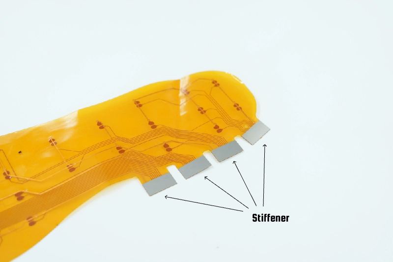
Stiffener
In stretchable PCB, stiffeners are used to provide the necessary structural stability in specific areas and to provide sturdy support for a soldered component. Stiffener materials include PI, FR4, Aluminum and Stainless Steel. Stiffeners typically range from 0.002 inches to 0.059 inches, in thickness. It's worth noting that not all printed circuit boards necessarily need stiffeners.
The following are situations where stiffeners need to be added to flexible PCBs:
●Need to provide mechanical support for SMD or PTH components in the flexible area.
●Need to maintain flatness and stability in certain areas of the flexible PCB.
●Need to meet Zero Insertion Force (ZIF) connection specifications.
●Need to increase board thickness.
●Reinforcement of connectors that require multiple insertions to minimize pad stresses.
Types of Flexible PCB Stiffeners
1. PI Stiffeners
PI stiffeners are typically around 0.002, to 0.010 inches thick. Are commonly employed to support gold fingers. Various thicknesses of PI can be chosen for press fitting based on the use case. PI is resistant to high and low temperatures and is flame retardant,, making it a popular choice in aerospace, microelectronics and laser applications.
2. FR-4 Stiffeners
FR4 has excellent electrical and mechanical properties but has less abrasion resistance than PI. It is typically used to support the backside of the SMD solder area to prevent damage to the SMD due to the bending of the area. In general, FR-4 stiffeners are the fastest and most economical choice.
3. Aluminum Stiffeners
Aluminum has good durability and thermal conductivity, so aluminum stiffeners are commonly used in lighting fixtures, aerospace parts, and automotive parts; these heat dissipation requirements of higher products.
4. Stainless Steel Stiffeners
Common materials of stainless steel stiffeners are 301, 303, 304, and so on. It is characterized by conductivity, high strength, not easy to deform, and high surface finish. It is also commonly used on the back of gold fingers to increase their thickness and hardness. At the same time, and other traditional FPC reinforcement board is different, steel plate reinforcement is not stamping process but chemical etching process. The chemical etching process has higher precision, smaller tolerances, and does not produce burrs that cause short circuits in the bendable PCB.
Manufacturing Process of Flexible PCBs
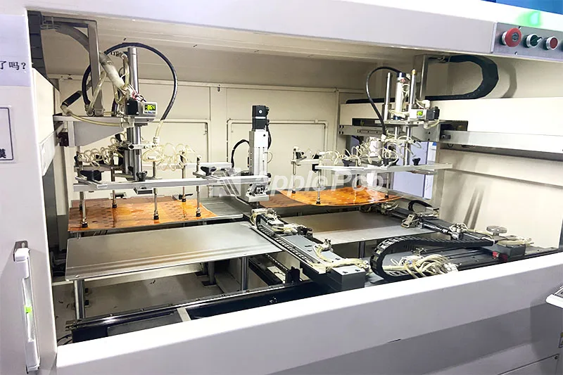
1. Design Flex PCB Structure and Layout
Before we start flex PCB fabrication, we check and analyze the customer's files using EDA PCB (usually we use Genesis2000) design software according to the FPC's application needs and customer requirements. This process involves issues such as dimensional shapes, alignment, through holes, component layout, etc...
2. Material Preparation
High-performance flexible PCBs mainly use polyimide (DuPont, Grace, Sheng Yi, etc.) as the substrate, these materials have good flexibility and heat resistance.
3. Press-laminated Copper Foil
By means of adhesives or chemical deposition, etc. The PI is laminated onto the copper foil to achieve electrical conductivity. Flexible PCB suppliers also have the option of purchasing already pre-fabricated copper-clad PI and use it directly to save flex PCB manufacturing time.
4. Drilling
Unlike Rigid PCBs, flexible PCB are usually not mechanically drilled but rather laser drilled to prevent damage and deformation of the soft material. These holes are used to insert components or connect different layers.
5. Cleaning
After drilling, we need to remove the burrs and residues generated during the drilling process.
6. Chemical Copper Immersion
At this time, the hole is not conductive. Flex PCB manufacturer need to make the hole wall through a chemical reaction to deposit a layer of copper, so as to realize its conductivity.
7. Image Transfer
This step is like printing out the pattern of a circuit on copper foil. A special material called photoresist is usually used that cures under ultraviolet light. This material covers the copper foil before exposure, and then the pattern is printed onto the it by exposure.
8. IPQC
After the line is completed, ApplePCB will test the wiring diagram to ensure the clarity of the wiring diagram and prevent the phenomenon of broken or short circuit.
9. Etching
The entire film is put into a chemical solution that will etch the copper foil portion that has no protective film (cured photoresist). This is like using a chemical solution to "bite off" the copper you don't need, leaving only the circuit patterns you want.
10. Pressing the Covering Layer
After the etching, we have to press the PI film and the circuit board through heat and adhesive. This layer of PI film is equivalent to the solder mask of Rigid PCBs, which plays the role of insulating and protecting the circuit.
11. Electroplating
Electroplating involves thickening the copper layer inside a hole through a process based on deposited copper. This ensures that the copper layer, on the hole wall has thickness and conductivity.
12. Surface Treatment
Surface treatment is mainly for pads and copper trace lines by plating a layer of protective metal, such as gold, silver, or tin, to prevent oxidation and improve solderability.
13. Screen Printing
Through the screen printing machine, the screen printing ink is evenly distributed and accurately positioned to form printed marks, words, and symbols. Finally, through drying and curing treatment, the screen printing ink is firmly adhered.
Assembly Process of Flexible PCBs
1. Bill of Materials (BOM)
The BOM (Bill of Materials) will list all the types, quantities, and details of components required for assembly. An accurate BOM helps avoid problem like component shortages or incorrect usage during production. In addition, ApplePCB as a one-stop flexible PCB supplier, we also offer electronic components sourcing service.
2. Baking
Before installing flexible PCB, it's essential to bake out moisture from moisture sensitive component, adhesive, and insulating material. This step help prevent soldering defect caused by moisture expansion during the reflow soldering process. ApplePCB ensures the temperature is kept within a safe range, typically below 120°C, to avoid damage to the components or the flexible PCB from excessive heat.
3. Solder Paste Printing
The solder paste is accurately and uniformly applied to the pads to be soldered by means of a customized SMT stencil in preparation for the subsequent placement.
4. Component placement
Using a high precision mounter, SMDs are accurately placed on pre-painted solder paste pads. In mass production, ApplePCB usually uses high-speed placement machines(placement speed is generally 100,000 CPH).
5. Reflow Soldering
The FPCs are passed through the reflow oven after the components are mounted. The temperature profile in the oven is designed to ensure that the solder paste melts at the proper temperature. Once the soldering is complete, the solder paste cools and solidifies, securing the component.
Due to the flexibility of the FPC, ApplePCB recommends that you use a forced hot air convection infrared reflow oven to prevent deformation of the intermediate area due to hot air and to ensure a uniform change in temperature on the FPC to minimize the occurrence of soldering defects.
6. Cleaning
After reflow soldering need to use a special cleaning agent to clean the board to remove excess flux residue to ensure that the board is clean.
7. Inspection and Repair
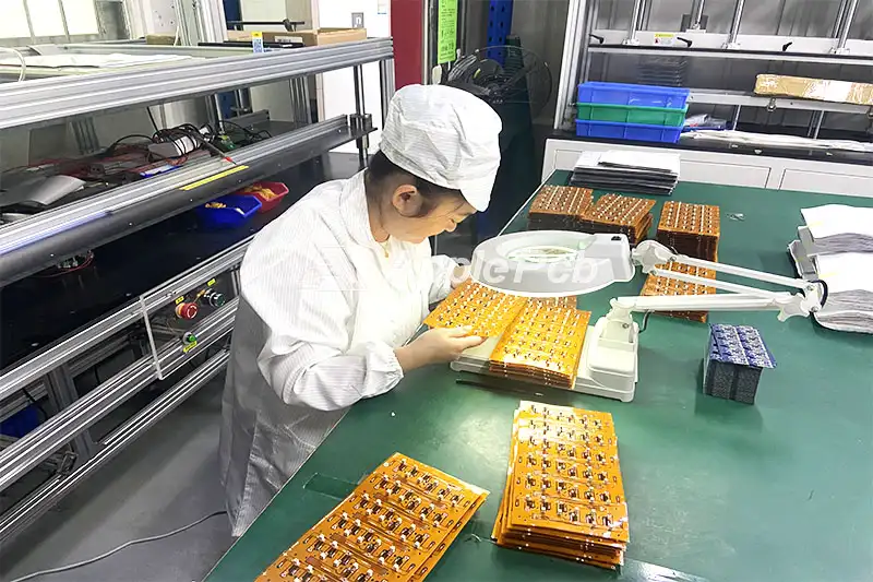
Flexible circuit board suppliers carry out quality checks on the boards. Any detected issues are either manually repaired or the boards are discarded. ApplePCB uses advanced Automated Optical Inspection (AOI) and X-ray inspection equipment. We conduct visual quality inspections and ICT (In-Circuit Test) online testing on flexible circuit boards to ensure both soldering quality and mounting precision.
8. Function Test
Functional tests are performed on the assembled FPCs to verify their electrical performance and reliability and to ensure that the products meet the design requirements and customer specifications.
Difference Between Flex PCB, Rigid PCB and Rigid-flex PCB
1. Materials: Rigid PCB utilize substances like FR-4, ceramics and metals. flex PCB Boards are crafted from materials such as polyimide and polyester. Rigid-flex PCBs bring together the substrates.
2. Conductive Materials: For conductive materials, Rigid PCBs utilize Electro Deposit (ED) processes, whereas Flex PCBs typically use rolled and annealed (RA) methods. Rigid-Flex PCBs use a combination of both techniques to suit their hybrid nature.
3. Insulation Materials: Rigid PCBs typically use epoxy resin for their robustness. Flex PCBs, on the other hand, prefer polyimide due to its flexibility. In rigid-flex PCBs, matching insulation material to the specific needs of each section.
4. Surface Finishing: Rigid PCBs offer a variety of surface finishes including HASL, ImSn, ENIG, OSP, ImAg, and Electrolytic Nickel/Gold, catering to diverse application needs. Flex PCBs typically use only ENIG, which provides a flat surface and prevents oxidation.
5. Copper Thickness: Copper thickness depend on the type of printed circuit board. Rigid PCB usually have copper thicknesses between 1 and 6 oz, but heavy copper board can be as thick as 20 oz. Flexible PCB have thinner copper layers, typically from 1/3 to 3 oz, to maintain flexibility. In rigid-flex PCB, due to the laminated structure, copper thickness can vary between layers, generally ranging from 1/2 to 6 oz.
6. Layers: In order to prevent structural asymmetry, resulting in warpage problem, the number of layers in a rigid printed circuit board is generally limited to an even number. Commonly 2, 4, 6, 8 layers, up to 36 layers. And flexible circuit board can be an odd number of layers. However, the number of layers of flexible circuit boards is usually low, usually no more than six layers, because too high a number of layers may lead to a weakening of flexibility. Rigid-flex PCB, on the other hand, can have anywhere from 4 to 18 layers and often require multiple layers to accommodate complex designs.
7. Flexibility and Durability: Hard PCBs are more rigid and less likely to break. On the contrary, flexible PCBs offer flexibility and can endure about 200,000 bends without peeling or distorting. Rigid Flex PCBs blend the benefits of flexibility and durability.
8. Stiffeners: Stiffeners used in Flex PCBs or R-FPC can include materials such as PI, FR4, Aluminum and Stainless Steel., providing structural support where needed without compromising the flexibility significantly. There are no stiffeners in Rigid PCB.
ApplePCB Manufacturing Capabilities
| ApplePCB FPC Manufacturing Capabilities | |
| Feature | Parameters |
| Material | PI, FPC, FCCL |
| (35µm Cu + 25µm PI + 35µm Cu) Dupont | |
| Structure | Flexible&Flex&Soft |
| Layer Count | 1-8 Layers |
| FPC Thickness | 0.002” – 0.1” (0.05-2.5mm) Including Stiffener Thickness |
| Coverlay | Single or Double Sided Yellow, Black |
| Silkscreen | Single or Double Sided White |
| Surface Treatment | ENIG |
| Finished Copper Weight | 1/3oz – 3oz |
| Min NC Drilling Dia | 0.2mm |
| Stiffener | PI, FR4, AL, 0.06mm steel stiffener |
| Minimum Trace/space | 3Mil/3Mil |
| Delivery Time | 1-2 Weeks |
| Quality Standards | IPC ;ROHS |
| Production Capacity | Up to 10,000 sqm per month |
| Certifications | IATF 16949:2024 |
| ISO 9001:2015 | |
| ISO14001:2015 | |
| ISO13485:2016 | |
| UL:ZPMV8. E522850 | |
| Customer Support | 24/7 Technical Support |
Why Choose ApplePCB?
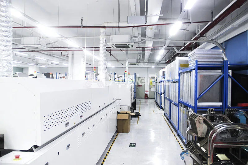
As a leading flex PCB supplier, ApplePCB provide one-stop solutions including electronic components sourcing, prototyping, mass production and flexible PCB assembly.
● High-Quality Materials
We can provide quality materials such as DuPont and Rogers, which have excellent flexibility, thermal stability and electrical properties.
● Competitive Price
We have our own flexible PCB manufacturing facility and 8 SMT lines, which gives us an efficient production process and competitive pricing.
● Advanced Manufacturing Capabilities
We specialized in small pitch, micro via technology, and multilayer flexible PCBs to meet the most demanding design requirements precisely.
● Fast Engineering Support
Our engineering team can provide EQ and production working files in less than a day, ensuring that your project moves accurately and quickly into production.
● Superior Customer Service
Our dedicated customer service team supports you throughout the process and provides comprehensive post-sales support.
Consider selecting ApplePCB as your trusted flex PCB supplier. Reach out to us now to kick off your project! Contact us today to get started on your next project.
