With progress leading to smarter, smaller and lighter devices, the adoption of rigid-flex PCB has now extended to the realms of medical devices and consumer electronics gradually gaining ground in a broader market. This article will cover the types, stacking, design, manufacturing, and manufacturers of Rigid-Flex PCB
What Is a Rigid-Flex PCB?
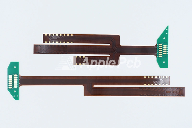
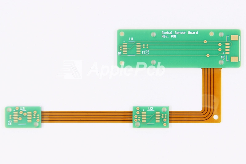
Rigid Flex PCBs are also called semi flex PCB and rigid flexible PCBs. It consist of one or more rigid and flexible sections. Rigid sections typically use materials such as FR4 to provide strong mechanical support and component mounting areas, while flexible sections use materials such as polyimide (PI) or liquid crystal polymers (LCP) to allow the board to bend and fold to accommodate three-dimensional spatial layouts. This hybrid structure allows the board to realize complex circuit designs and high-density wiring in a compact space. However, their exceptional features also bring about challenges during the design and manufacturing processes.
By choosing ApplePCB as your rigid flex PCB manufacturer, you can take full advantage of our advanced manufacturing technology and extensive industry expertise.ApplePCB's raw materials(SYTECH, TUC, ITEQ, KB, DuPont), production equipment(Han's Laser、Panasonic、Juki), and electronic components are sourced from reputable brands, which guarantees the quality of the PCB. We provide a one-stop service from customization to mass production of rigid-flex PCB. Our products meet aerospace, medical, automotive electronics, and military standards and have been leading the industry.
Rigid-Flex PCB Types
Rigid Flex circuit boards can be classified into various types using different criteria. For different types of Rigid-Flex PCB, ApplePCB has rich experience.
Classification by Flexible Layers
1. Only one flexible layer type:This Rigid-Flex PCB has only one flexible layer that may be used to connect rigid areas. It is cheaper to rigid-flex PCB fabrication and is mainly used in consumer electronics.
2. Multi-layer flexible layer type:These pcbs utilize a multi-layer sandwich construction with flexible layers (which can include two or more flex layers) between each pair of rigid layers. Typically used in aerospace, military, advanced communication systems, and high-end medical devices, which require the highest levels of performance, reliability, and complex circuit designs.
Classification by Type of Flexibility
1. Flexible mounting type: If you only need to fold and bend the board once, then the flexible mounting type is more suitable for you. It has simpler material,design requirements, lower cost, so is suitable for internal connections in some consumer electronics and medical devices.
2. Dynamic Flex: If you need these boards to be able to bend and move repeatedly, then Dynamic Flex is a better choice. They can fulfill applications for robotic arms, wearable devices and certain high-end medical devices. ApplePCB's Dynamic Rigid-Flex PCB are rigorously tested to ensure optimal performance and reliability over thousands of bends.
Difference Between Rigid-Flex PCB and Hybrid PCB
Regarding materials, rigid-flex PCB are usually made of the flexible material PI and the rigid material FR4. Hybrid printed circuit boards, on the other hand, are not limited to a combination of rigid and flexible materials but can include a wide range of materials (FR4, Rogers, aluminum, copper, polyimide, PTFE) to meet specific needs such as high frequency, high speed, mixed signal, and so on.
From a rigid flex PCB manufacturing perspective, both involve different materials, so extra attention should be paid to the differences in CTE values, thickness, and mechanical strength of the different materials to prevent problems such as inconsistent hole-wall plating, delamination, deformation, and warpage.
The degree of influence of these factors may vary for different materials. If you plan to use a hybrid PCB or Rigid-Flex PCB stacked design, we recommend that you contact ApplePCB as early as possible. We have the manufacturing experience and expertise to handle designs in different materials combined with standard FR4 materials.
ApplePCB Rigid-Flex PCB Manufacturing Capabilities
| Capability | Details |
| Number of Layers | 4-40 Layers |
| Build Time | 1-2 Weeks |
| Polyimide Base Material | Polyimide(PI), PET, Polyester-Flex |
| Rigid Base Materials | Rogers, ISOLA, Nelco, Taconic, Shengyi etc. |
| FPC Thickness | 0.1 – 0.6MM |
| Rigid Thickness | 0.4 – 5.4MM |
| Min Track / Spacing | 3Mil |
| Min Hole Size (diameter) | 0.1MM-0.2MM |
| Hole to flex | Minimum 30 mil |
| Coverlay (Flex Part) | Yellow Coverlay,Black Coverlay, White Coverlay, |
| Silkscreen Color | Yellow, Red, White, Black, Etc. |
| Surface Finish | OSP, Plated Gold, Immersion Gold, Immersion Silver, Immersion Tin, etc. |
| Finished Copper | 0.5 oz – 6 oz |
| Stiffener Material | FR4, Steel, Aluminum and PI |
| Assembly Techniques | High precision mounter, |
| Reflow soldering, | |
| Selective soldering | |
| Certifications | IATF 16949:2024 |
| ISO 9001:2015 | |
| ISO14001:2015 | |
| ISO13485:2016 | |
| UL:ZPMV8.E522850 | |
| Quality Standards | IPC ;ROHS |
How to Design a Rigid-Flex PCB Stack?

Designing a rigidflex PCB stack-up requires careful consideration of both the rigid and flexible parts of the board. Here are the essential steps and guidelines for creating a robust and reliable rigid-flex PCB:
1. Understand the Structure
A typical rigid-flex PCB combines rigid and flexible layers to take advantage of both technologies. It usually involves multiple layers of flexible circuit substrates attached to rigid boards either externally or internally, depending on the application requirements
2. Material Selection
The flexible part of the rigid-flex PCB typically uses a pliable polyimide core, which is surrounded by copper foil for signal conduction. The rigid sections are often composed of FR-4 laminate. The choice of materials should consider factors like thermal performance, flexibility, and durability.
3. Layer Stack-Up
The stack-up process involves defining the sequence and materials for each layer. A common design includes a four-layer process where the core polyimide is surrounded by copper, with FR-4 laminate layers above and below. This configuration provides a balance between flexibility and rigidity.
4. Manufacturing Process
The fabrication of rigid-flex PCB is more complex than standard rigid boards or flexible boards. It involves additional steps for handling, etching, and soldering the flexible components. Engaging with your manufacturer early in the design process is essential to ensure that the design can be produced reliably and efficiently.
Issues to Be Considered When Designing Rigid-Flex PCB
When designing a stack of Rigid-Flex PCB there are a number of key considerations that need to be taken into account to ensure the rigid-flex PCB cost and performance. We'd be happy to help you improve your design process by calling +86 0755-23597580 or speaking with one of our expert staff members in the lower right corner. Here are some key points to keep in mind:
Stack Design
Proper stacking design is the basis for manufacturing rigid-flex boards. A complete Rigid-Flex PCB usually has several different stacking designs, which means that different areas of the Rigid-Flex PCB, may have different thicknesses and structures. Generally speaking, the rigid part has a thicker stacking structure to facilitate the stable installation of components, while the flexible part has a thinner stacking structure to facilitate bending and folding. Material's thermal expansion and mechanical properties also need to be considered in the stack-up design to improve durability under stress conditions and prevent delamination.
Material Selection
When selecting a material, it is important to consider factors such as electrical properties and mechanical characteristics to ensure optimal performance across various applications. The following materials are commonly used for PCB rigid flex:
● Substrates
Choosing the right substrate material can ensure the stable operation of the product. ApplePCB offers a wide range of substrate materials to choose from, such as FR-4, PI, and LCP. The commonly used materials for Rigid-Flex PCB are FR-4 and PI. FR-4 is a composite material made by combining glass fiber and epoxy resin, which has excellent mechanical strength and electrical properties, but it does not resist frequent vibrations and shocks well, so it is commonly used for rigid parts.
PI, on the other hand, has excellent flexibility and thermal stability, fixing the disadvantage of FR-4, which is used in flex areas. Another flexible material is liquid crystal polymer (LCP). Compared to PI, LCP has a lower dielectric constant ε_r(1GHz) of 2.85 (PI is typically 3.4), giving it superior signal transmission. At the same time, the moisture absorption rate of LCP is only 0.04%. These advantages make it ideal for high-humidity environments and high-frequency applications. You can contact us for a more in-depth understanding to help you select the right substrate.
● Conductor Materials
The common conductor material used for Rigid-Flex PCBs is copper, but some inexpensive electronics can also use printed conductors (carbon film/silver-based ink) to save money.
Copper has good electrical conductivity, but it is also prone to fatigue from repeated bending or movement. So, depending on the application, ApplePCB can provide you with either electrolytic copper (ED copper) or rolled annealed copper (RA copper). ED copper has a lower cost and is suitable for static applications where bending is only required once.
RA copper is treated with a rolled annealing process despite the added cost of the process, which significantly improves the ductility and fatigue resistance of the copper. Because the rolled annealing process elongates the grain structure of the copper, the copper foil can be stretched longer, providing greater flexibility in the direction of Z-axis deflection. This makes RA copper suitable for use in dynamic bending applications that require continuous bending.
In addition, a thin layer of zinc is usually applied to the copper foil prior to circuit board assembly to prevent oxidation, improve adhesion, and enhance the strength of the copper foil.
● Adhesive
When bonding copper foil to PI (or other films), we need to use an adhesive. This is because, unlike FR4 rigid boards, the surface of annealed copper foils lacks sufficient roughness, and heat and pressure alone are not sufficient to form a strong bond.
For this reason ApplePCB offers pre-laminated single and double sided copper clad films, typically with acrylic or epoxy based adhesives in 1/2 mil and 1 mil thicknesses. It's worth noting that ours uses an epoxy adhesive with a small amount of polyester added, which makes it even more flexible.In addition, we offer polyimide adhesives and modified polyester adhesives with excellent high-temperature resistance.
Bending Design
As we have mentioned before, Rigid-flexible PCBs can be categorised into flexible mounting and dynamic, flexible types. The former flexes only once during installation and is held in one position. The latter can be bent many times during use and should, therefore, be designed to minimise the number of flexible layers. Engineers must calculate the bends' radius, position and direction at the design stage. You can use the equations in IPC-2223 (Equation 1 for one side, Equation 2 for double sides, etc.) to determine the minimum bend radius allowed for a flexible section based on the allowable deformation of copper and other material properties.
Typically, a smoother bend radius and thinner thickness should be selected, and we recommend keeping the bend radius to thickness ratio at 10:1.
Component Layout
Proper component layout can significantly enhance the thermal performance and signal integrity of the board. Components should be placed as close as possible to the relevant connection points to reduce the signal path length and minimise interference between high-frequency components. Heat-dissipating components should be located in areas that maximize heat dissipation. Additionally, vias and components should not be placed in bend areas, known as Via keepout and Component keepout , to avoid mechanical stress and potential damage.
Wire Layout and Shape
The design of the conductor layout and shape has a significant impact on the performance of the board. Conductors should avoid sharp 45°or 90°turns but use curved alignments, and teardrop graphic transitions can also be used when changing alignment widths to minimize signal reflections and interference.
For dynamic double-sided flexible circuits, the traces should be staggered between adjacent layers to prevent overlap. Staggering the traces between layers ensures that the stresses are more evenly distributed across the flexible substrate during bending, thus reducing the risk of overstressing a single layer. In this way, the reliability and durability of flexible circuits can be effectively improved.
Via Design
The Through-hole is an important part of connecting different layers of the board, and its design is related to the performance of the rigid-flexible boards. We should try to avoid placing via holes in flexible areas, as copper is susceptible to fatigue under repeated bending and folding, which may ultimately affect the conductivity of the through-hole. It is possible to place via holes in rigid areas, but care should be taken to avoid placing via holes in the edge area (ensure 50 mil distance).
Issues to Be Considered When Rigid-Flex PCB Manufacturing

Once the Rigid-Flex PCB design is complete, the next step is to proceed with manufacturing. This stage calls for manufacturing expertise to guarantee that the boards manufactured meet standards of quality and dependability. Here are a few critical considerations and steps during rigid-flex PCB fabrication.
Preparing Materials
After selecting the materials, we need to thoroughly clean all the materials to avoid tiny contaminants affecting the bonding effect and electrical performance. ApplePCB has introduced advanced ultrasonic cleaning equipment to ensure that the surface of the materials is absolutely clean, which lays a good foundation for the subsequent process.
Exposure and Development
Once the materials surface is thoroughly cleaned we apply a coating using high-precision coating equipment. To avoid issues, like low image quality and unclear graphics commonly seen with tradional exposure methods ApplePCB utilizes state of the art LDI equipment sourced from Daqo Laser to guarantee precise graphics. This modernized production process allows us to achieve a minimum line width and line spacing of 3 mils.
Drilling and Plating
ApplePCB's Mitsubishi laser drilling machine is able to achieve a minimum hole size of 0.1MM and ensures excellent hole wall quality and precision by reasonably designing the drill bit and feed rate to prevent leakage, burrs, uneven quality, and other problems. After drilling, PCBs go through an automated plating line, where we precisely control the plating thickness to ensure uniform copper plating for each through-hole and stable interconnection of rigid and flexible layers.
Lamination
By using adhesive films and high temperatures and pressures, we can laminate rigid and flexible materials together. Precise alignment and lamination pressure are critical in this process. This requires the use of highly accurate laminators and strict control of the laminating temperature and pressure to ensure consistent and reliable laminate quality.
Surface Treatment
The copper layer on the surface of the board needs to be treated with anti-oxidation to prevent oxidation problems during subsequent use. Enhance the durability and solderability of Rigid-Flex PCB.
Final Molding
With the help of laser cutting equipment, we precisely cut and V-cut the circuit boards. The cut edges are carefully inspected during this process to ensure that the conductor extends correctly to the edge and that there are no scratches or damage. These checks are performed by experienced technicians to ensure the quality of each rigid flex circuit board.
Component Assembly
During the assembly process, special attention needs to be paid to the protection of flexible parts to avoid damage caused by bending or other mechanical stresses. SMT and through-hole assemblies are only carried out in rigid areas. With the help of high-precision and high-speed mounters, we can realize fast and accurate assembly of components.
Testing and Inspection
ApplePCB has specialized testing sessions for different problems that may occur, ensuring good electrical and mechanical properties of Rigid-Flex PCB.
● Electrical testing: troubleshooting short circuits, broken circuits, and other problems.
● Automatic Optical Inspection (AOI): Ensure the correct position of components, solder joints, and lines.
● X-ray inspection: non-destructive inspection of BGA and inner through-hole quality.
● Bending cycle test: ensure that delamination and cracks will not occur in multiple bending.
How to Find a Reliable Rigid-Flex PCB Manufacturer?
When searching for a manufacturer of flex PCB consider these key factors:
Industry Experience
Generally speaking, manufacturers of Rigid-Flex PCB with more than ten years of experience are more trustworthy.
Manufacturing Capability
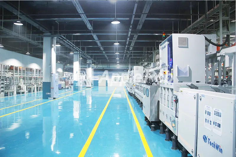
Professional rigid-flex PCB manufacturers typically maintain websites showcasing their PCB production capabilities featuring videos of their production processes and other relevant details. If you have doubts, about the reliability of interactions you can opt to visit the factory for a more hands on assessment.
Quality Control
When selecting a supplier opt, for one that follows quality control in line with standards like ISO 9001 certification. For industries like medical and automotive that demand top notch quality ensure the products also carry industry certifications such as ISO 13485 (for equipment) or IATF 16949 (for automotive manufacturing).
Customer Support
Choosing for a manufacturer to provide technical assistance and attentive customer service to ensure that you receive the necessary support, both pre-production and post-production.
Why Choose ApplePCB?

As a rigid-flex PCB manufacturer with 15 years of experience, ApplePCB has established an excellent reputation in the industry. We can provide you with:
Leading Technology and Experience
ApplePCB, as an expert in China's Electronic Manufacturing Services (EMS), has competitive factories, a wealth of industry experience, and advanced rigid-flex PCB manufacturing technology, providing customers with one-stop services from design to mass production.
Professional Team Support
Our team of more than 60 technical professionals, each with more than 10 years of experience in rigid-flex PCB, can provide expert advice on your design and help you solve your manufacturing challenges.
On-Time Delivery
With a 99% on time shipment record and support from reputable logistics partners like DHL, FedEx and UPS we guarantee prompt delivery of your project.
| Sample Delivery Time | Batch delivery time |
| 4-5 working days | 1-2weeks |
Quality Recognized by Global Customers
ApplePCB has received acclaim for top-notch quality from clients across various industries. With a clientele of over 3,000 customers in than 50 countries our presence spans North America, Europe, Asia and beyond. We serve an array of sectors including aerospace, automotive, medical devices, consumer electronics and telecommunications. Our dedication, to excellence guarantees that our Rigid Flex PCBs meet the standards of different fields.
Rapid Response Times
We offer 24/7 consulting services to ensure that our staff can respond to your message within 1 hour. Upon receipt of your Gerber documents, we guarantee to provide you with a competitive rigid-flex PCB price quote within 2 hours, allowing you to make an informed decision quickly. After the EQ is processed, we will expedite the production process and start production within 1 day to meet your tight deadline.
